PLASMALAB PECVD/RIE
Additional figures are at the end of this article.
SAFETY:
Toxic gasses can escape if proper vent and purge procedures are not
fully implemented.
Wafer stages can be extremely hot.
INTRODUCTION:
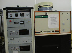
The Plasmalab PECVD/RIE is designed with two chamber modules and a common
process controller: deposition of materials in the PECVD module and etching
in the RIE module. Because a single process controller is used for both
modules, only one module can be operated at a time. However, both chambers
must be under vacuum before any module's process will execute.
CAUTION: Loading wafers onto a hot wafer stage may cause them
to break.
CAUTION: Opening the chamber before it is fully vented will result
in chamber contamination caused by the reactions of unvented process gasses
and ambient air.
The contamination renders the machine unusable until it has been laboriously
cleaned by hand. Wait until the vent light stops flashing before opening
the chamber.
Process Controller:
-
Process:
-
Sequence of up to eight control steps.
-
Step:
-
Execution of a set of chamber control process parameters.
Process Controller Parameters:
-
Rough pressure (mTorr):
-
The chamber pressure at which HIVAC begins.
-
HIVAC (seconds):
-
Time to continue pumping after rough setpoint.
-
Throttle pressure (mTorr):
-
Chamber pressure during a step.
-
Gas selections (% of maximum):
PECVD GAS                             MAX RANGE
Gas 1   Nitrous Oxide (N2O)            20 sccm
Gas 2   Ammonia (NH3)                  20 sccm
Gas 3   Methane (CH4)                   ? sccm
Gas 4   Silane (SiH4)                 200 sccm
Gas 5   Sulfur Hexafluoride (SF6)       On/Off

RIE GAS                               MAX RANGE
Gas 1   Sulfur Hexafluoride(SF6)       20 sccm
Gas 2   Methane (CH4)                  20 sccm
Gas 3   Oxygen (O2)                    50 sccm
Gas 4   Argon (Ar)                     50 sccm
Gas 5   Hydrogen (H2)                  On/Off

Note:   Gas 5 is for chamber cleaning and is controlled by a
flow meter located on the gas pod. The flow for gas 5 should
not be readjusted.
-
RF Power (% of maxiumum):
-
Radio frequency power during a step.
-
Heater (oC):
-
Wafer stage heat set point should be ZERO: setpoint at temperature controller.
-
Time (minutes.decimal):
-
Step duration.
-
Pause (minutes.decimal):
-
Time period at end of process before venting.
-
Vent (0%/100%):
-
Yes/No purge-vent cycle at end of process.
PARAMETER STACKS
-
Data Stack:
-
Parameter values used for a processing run.
-
Memory Stack:
-
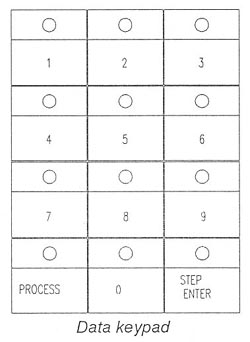
Stored process parameter values. Copy to the Data stack by pressing PROCESS
and the numeric process ID key.
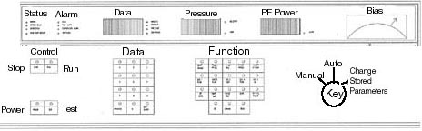
MODE Keyswitch
-
Auto:
-
Automatic execution of the Data Stack steps.
-
Manual:
-
Change (temporary) process parameter values copied from Memory Stack to
Data Stack. Real-time control of parameters during run.
-
Change Stored Parameters:
-
Change (permanent) process parameter values.
PROCEDURE
-
Every run must be entered in the logbook.
-
Module keyswitch to MASTER/PECVD or SLAVE/RIE.
-
Mode keyswitch to MANUAL.
-
Press MANUAL and VENT to start the vent cycle. Wait for the VENT key light
to stop blinking.
-
Open the chamber by pressing the Black Pneumatic Push Button and moving
the Toggle Switch to the Up position.
-
Place wafers on the wafer stage.
-
Close the chamber by pressing the Black Pneumatic Push Button and moving
the Toggle Switch to the down position.
-
Select the process to run by pressing PROCESS and the numeric key process
ID. Then press STEP and 1 (one).
-
Mode keyswitch to CHANGE STORED PARAMETERS.
-
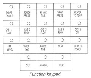
Review each process parameter in turn by pressing READ and the target function
keys.
-
Mode keyswitch to MANUAL.
-
Change (temporarily) process parameters as needed (notably, time) by pressing
SET and the target parameter key, and then entering the parameter with
the data keypad and pressing ENTER.
-
Mode keyswitch to AUTO
-
Start the process by pressing Run.
-
When process is complete, mode keyswitch to MANUAL.
-
Vent and open chamber as described above. Remove the wafers, taking care
as the wafer stage is at 300oC.
-
Close chamber as described above.
-
Press Manual and Rough keys.
-
Turn off temperature controller by pressing its red (off) button.
PECVD Stored Standard Processes:
Do not change the stored standard processes.
Make temporary parameter changes with keyswitch at MANUAL.
-
Process # 1 - Silicon Oxide (SiO2) - One Step
-
Gas 1 N20 = 12 sccm (60%)
-
Gas 4 SiH4/N2 = 64 sccm (32%)
-
Total Chamber Pressure = 300 mTorr
-
Substrate Temperature = 0 (300oC at temp. controller)
-
RF Power = 10W (4.4%)
-
Deposition Rate = 165Å/min.
-
Time = Operator Specified.
-
Refractive Index = 1.5
-
Process # 2 - Silicon Nitride (Si3N4) - One Step
-
Gas 2 NH3 = 5 sccm (25%)
-
Gas 4 SiH4/N2 = 200 sccm (100%)
-
Total Chamber Pressure = 350 mTorr
-
Substrate Temperature = 0 (300oC at temp. controller)
-
RF Power = 20W (7.8%)
-
Deposition Rate = 100Å/min.
-
Time = Operator Specified.
-
Refractive Index = 2.0
-
Process # 3 - Chamber Clean - Four Steps
-
Note : Process 3 parameters require no modification.
Cleaning interval is 30 kÅ, cumulative.
-
Gas 5 SF6 = ? sccm (100%) all steps
-
Total Chamber Pressure = 750 mTorr - 150 mTorr - 750 mTorr - 150 mTorr
-
Substrate Temperature = 0 (300oC at temp. controller) all steps
-
RF Power = ?W (67%) all steps
-
Time = 45 minutes all steps
| FUNCTION |
MODE KEYSWITCH |
| |
AUTO |
MANUAL |
CHANGE STORED PARAM |
| SET |
--- |
Data Stack |
Memory Stack |
| MANUAL |
--- |
Func on/off |
--- |
| READ |
Setpoint
---
Process Data |
Setpoint
---
Process Data |
Memory Stack |
Micro "P" DP s/n SF7-9071
Micro "P" RIE s/n SF7-9074