

Simulation of a Lock-in Amplifier

[Operating instructions] [Mathematical basis of this model] [Suggested experiment]
[Operating instructions] [Mathematical basis of this model] [Suggested experiment]
Real-time simulation of a lock-in
amplifier, an electronic instrument used to measure the
amplitude of weak periodic signals buried in noise. Unlike a real
lock-in amplifier, this simulation shows the waveforms of the
input signal, the reference signal, and the unfiltered output
signals, as well as the low-pass filtered DC output signal which
is the normal output of a lock-in amplifier. There is also a
companion AC volmeter simulation to
compare to the lock-in. For a simulation of a lock-in written in
Matlab/Octave, see https://terpconnect.umd.edu/~toh/spectrum/CaseStudies.html#Modulation
Download links: Version 1.0 of Lockin1.wkz;
Version 1.0 of AC voltmeter;
Wingz player application and basic set
of simulation modules, for windows PCs or
Macintosh
Other related simulations:
Wavelength modulation system
Modulation
and synchronous detection (in Matlab/Octave)
Click the "Run" radio button (on the right of the screen) to start the real-time simulation. Click "Pause" to freeze the display. The characteristics of the input signal are controlled by the red box labeled "Input signal" on the left; click on the up and down arrows to increase and decrease the values of input signal voltage, the random noise, and the flicker (low-frequency additive noise). The total input signal waveform is shown in the left-hand graph as the red line.
You can control the the gain of the lock-in amplifier and the phase shift of the reference signal with the controls in the middle (blue) box. The reference signal waveform is shown in the left-hand graph as the blue line. The waveform of the output of the synchronous detector is shown in the right-hand graph. (This waveform equals the input signal times gain when the reference signal is positive and equals the negative of the input signal times gain when the reference signal is negative).
The output of the lock-in amplifier is shown in the box labeled "Output" on the right. The "Output voltage" is the DC voltage resulting from low-pass filtering the output of the synchronous detector. The signal-to-noise ratio and the relative standard deviation of the output voltage is also shown here. The response time of the output voltage is about 1 second when the simulation is run on a 450 MHz pentium.
1. Click on the "run" radio button on the right of the screen to begin the real-time simulation. Start with noise = 0, flicker = 0, gain = 1, and phase = 0. Vary the input voltage and look at left-hand graph. The red line is the input signal waveform, which varies in height as you vary the voltage. The numeric values of the voltage is in RMS volts. The frequency of the waveform is about 80 Hz, when the simulation is run on a 450 MHz Pentium computer.
2. Now look at the right-hand graph; this represents the output of the synchronous detector, the circuit in the lock-in that converts the AC input waveform to DC. Note that in this case the synchronous detector acts like a full-wave rectifier, inverting the negative portions of the input waveform so that the output waveform is all positive.
3. Look at the output voltage displayed in the Output box at the top right of the screen. This is the result of feeding the output of the synchronous detector through a low-pass filter to convert it into a smooth DC voltage; it represents the average of the output signal. Note that this average voltage is slightly lower than the input RMS input voltage. (Theoretically, for a pure sine wave, 1.0 volt peak = 0.71 volts RMS = 0.64 volts average).
4. Vary the gain and note the effect on the output waveform and voltage. The gain control is used to accommodate a wide range of input voltages.
5. What is the purpose of the reference waveform and the phase control? A lock-in amplifier requires a reference waveform, a waveform that has exactly the same frequency as, and a fixed phase relationship to, the input waveform. This reference waveform is derived from the experimental apparatus, from the device that generates the AC waveform of the input signal. Lock-in amplifiers are most commonly used in experiments where the physical quantity being measured (light intensity, for example) is converted into an AC waveform by means of a modulation device (a rotating slotted wheel chopper or a modulated laser power supply, for example). The reference waveform is obtained directly from the modulation device (e.g. from the laser power supply or from a ancillary light bulb and photocell placed along the circumference of the rotating chopper wheel). Thus, the reference waveform is typically a clean, fixed-amplitude waveform that is "locked" to the signal waveform; if the signal waveform were to change in frequency (because the chopper wheel changes speed, for example) the reference waveform would change in exactly the same way, keeping itself perfectly "locked in" to the signal frequency.
The function of the reference waveform is to control the synchronous detector, a simple electronic circuit that passes the signal waveform unchanged when the reference waveform is positive and inverts (changes to polarity of) the signal waveform when the reference waveform is negative. You can verify that this is true by changing the "phase" control in the blue lock-in controls box. This controls a phase-shifting circuit in the lock-in amplifier that shifts the phase of the reference signal before it gets to the synchronous detector. Notice the effect on the blue (reference) waveform and on the output voltage. The phase shift between the signal and reference waveforms must be zero to obtain a maximum output voltage. But often the reference waveform derived from the experiment has some non-zero phase relationship to the signal. Therefore all lock-in amplifiers have a phase control so that this initial reference phase shift can be compensated and the output voltage can be optimized.
6. Now increase the "noise" control. This adds random wideband noise to the input signal, as you can see in the graphs. (In an optical experiment, photon noise would look like this). Notice that the output voltage fluctuates slightly (with a response time of about 1 second when the simulation is run on a 450 MHz Pentium and slower if it is run on a slower computer). The output RMS noise, signal-to-noise ratio (SNR), and relative standard deviation are all listed below the output voltage. Note how much lower the output noise is compared to the input noise - this is the result of the noise reduction by low-pass filtering. Set the input voltage to 0.07 volts and the noise to 0.08 volts; this makes the input SNR slightly less than 1.0; what is the output SNR in this case? Increase the noise even further. The output voltage begins to fluctuate more strongly as the noise is increased. What is the lowest input SNR that allows you to measure the output voltage with a relative precision (standard deviation) of 10%? Look at the input waveform in this case - can you see any hint of the sine-wave signal waveform in all that noise? This is why it is said that a lock-in amplifier can measure a the amplitude of a periodic waveform that is "buried" in noise.
7. The lock-in amplifier is even more successful at reducing flicker. Set the noise control to zero and increase the flicker control. This simulates the effect of low-frequency background flicker, a common source of noise in some types of spectroscopic measurement. Note that the flicker is reduced even more that the wideband (photon) noise.
8. At this point, it seems that a lock-in amplifier does little more than convert an AC input signal into DC. Isn't this what a rectifier circuit does also? Wouldn't it be simpler just to use a rectifier/filter combination rather than a synchronous detector, with all the complications of requiring a reference waveform. Indeed, this is just what a standard AC voltmeter does. Moreover, an AC voltmeter is cheaper. So why not use an AC voltmeter rather than a lock-in amplifier?
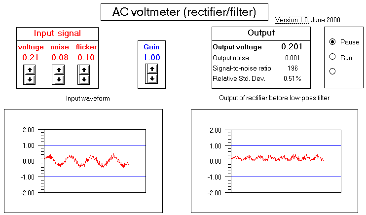
That's a good question, and to answer it, there is a companion simulation of a AC voltmeter that you can open along with the lock-in amplifier. (Download link: ACvolt.WKZ). This looks and works exactly like the lock-in amplifier, except that it has no reference input or phase control. You will discover that the AC voltmeter behaves just like the lock-in amplifier if the noise and flicker is zero and if the phase control of the lock-in is set to zero. So what the difference? The difference is in the behavior with respect to noise and flicker. Set the input signal voltage to zero on both simulators; the output voltage reads zero, of course. Now increase the noise on both simulators and watch the output voltage; the lock-in output begins to fluctuate slightly, but it fluctuates around zero, as it should. In contrast, the mean value of the AC voltmeter output actually increases as the noise increases, giving the erroneous impression that the input signal has increased. This is because the AC voltmeter is converting the noise into DC, as you can see by inspecting the rectifier output waveform (right-hand graph). The lock-in amplifier does not do this, because the noise is random and not synchronized with the reference waveform. This is a big advantage of the lock-in amplifier. The advantage is even more striking for flicker; turn up the flicker on both simulators and notice how the output voltage of the AC voltmeter responds to the flicker but that the lock-in is almost immune to flicker.
As a final test, set the noise to 0.8 and the flicker to 0.2 in both simulators. Now try to detect the difference in the output voltge between an input voltage of zero and an input voltage of 0.07 volts. This is an extremely challenging signal-to-noise situation. It's just possible to detect the difference on the lock-in but impossible on the AC voltmeter.