KARL SUSS MJB3-HP-IR
CONTACT ALIGNER
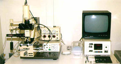
Additional figures are at the end of this article.
- SAFETY
- The system employs a high pressure mercury lamp. If a catastrophic failure of the
lamp should occur, avoid touching glass debris or inhaling mercury vapor fumes. Notify a
staff member at once.
- The UV light produced by the lamp can cause erythema of the skin (similar to
sunburn), conjunctivitis and possible retinal burn that could result in blindness.
Though the operator is protected from direct exposure to UV light it is recommended that
the operator does not look at the mask/wafer assembly at the time of the exposure;
indirect UV light may also harm the eye retina.
- SETUP
- Start Up : The aligner is normally not shut down after use; therefore it is
normally ready for subsequent alignment(s). If the aligner has been shut down, contact a
staff member to restart it,
or follow this link for the restart procedure.
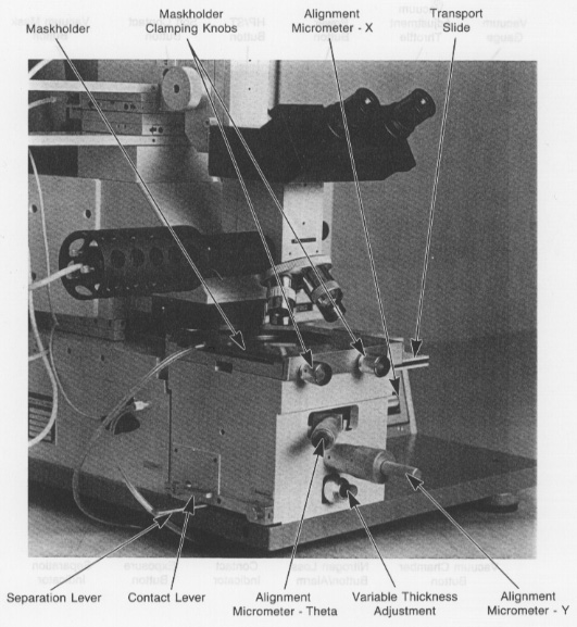
- Mask : Place the MASKHOLDER on a flat surface with the vacuum ring facing up.
Place the mask on the mask chuck with the chrome (pattern) side of the mask facing away
from the MASKHOLDER. Press the VACUUM MASK button. Invert the mask chuck and insert it
into the stage. Tighten the mask chuck clamp with the knurled screws on the left side of
the stage.
- Wafer Chuck : Chucks with metal tops are for topside alignments; chucks with
blue tops are for backside (IR) alignments. Chucks with rubber gasket rings are for
Vacuum Contact (HP) mode; chucks without rubber gasket rings are for Standard-Hard and
Standard-Soft contact modes.
- Wafer : Place a wafer chuck appropriate for wafer size, type of alignment
(front/back), and type of exposure (vacuum/regular) into the wafer chuck transport
slider. On it, place the wafer with the exposure side facing up and appropriately
positioned with respect to the mask. The back side of the wafer must be very clean
to avoid vacuum leaks at the wafer chuck. If the wafer (piece) doesn't cover all of
the wafer chuck vacuum holes, place cleaving tape over any open holes; however, do
not cover the chuck's channel groove or the vacuum breaker hole in the groove.
Carefully slide the wafer chuck transport slider home towards the stage.
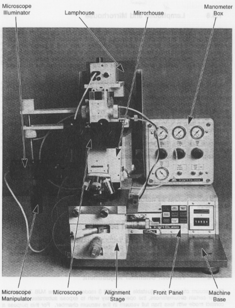
- Microscope Illuminator : Turn up the microscope illumination dial located
on the unit under the IR alignment TV monitor.
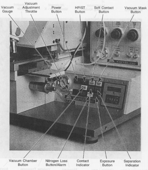
- CONTACT
- Set exposure mode (HP/ST/ST-Soft) before adjusting contact.
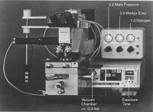
- HP Contact Mode : during exposure, a vacuum is drawn between the mask and
wafer.
- Vacuum Chamber : produces the HP contact prior to exposure so that
any shift in alignment can be visually identified prior to executing
an exposure sequence. The vacuum can be removed by moving the SEPARATION
LEVER to the separation position.
- ST Hard Contact Mode : during exposure, the vacuum holding the wafer
to the chuck is switched off and positive nitrogen pressure is used to press
the wafer against the mask.
- ST Soft Contact Mode : during exposure, the wafer is held to the mask
with mechanical pressure only, and the vacuum holding the wafer to the chuck
remains on.
- Microscope movement is made with the large manipulator lever at the left of the
aligner. It features two air brake buttons on the handle which, when depressed, allow
the movement in their respective x and y axis directions.
- Adjust microscope position where features on the mask and wafer through the mask are
in simultaneous field of view. Focus on mask feature(s). The most precise point of
contact will be acheived with the highest microscope magnification. Slowly raise the
wafer towards the mask by rotating the contact lever. As the wafer comes into the
microscope's focus depth of field, shadows will form on the wafer. Continuing to move
the wafer towards the mask will cause the shadows to disappear. At this point the
contact lever should be approximately 3/4 of its travel rotation distance towards the
rear of the aligner. Adjust the point of contact as needed with the "variable
thickness adjustment knob". When contact is made relative to the correct position of
the contact lever, complete the full rotational movement of the contact lever towards
the rear of the aligner (past the contact point). The CONTACT lamp will light. Lock
the contact adjustment knob.
- ALIGNMENT-TOPSIDE
- Separate the wafer from the mask with the SEPARATION LEVER at the left of the aligner
by moving the lever toward the front of the aligner. The CONTACT lamp will go out.
- Verify separation by rotating one of the stage motion micrometers. If the wafer
does not move freely, put the separation lever back into contact, move the contact lever
to lower the wafer from the mask (contact lamp will go out), unlock the "variable
thickness adjustment knob", and repeat contact adjustment for less contact.
- Approximate alignment with low power microscope objective. Near center of mask find
alignment mark(s) and use x-y-theta stage movement micrometers to move wafer
alignment mark(s) into approximate alignment with mask alignment mark(s). Then do the
same with alignment marks located near the x-axis limits of microscope movement.
- Finely adjust alignment by using higher power microscope objectives and alignment
marks located near the limits of x-axis microscope travel. Use the x-y axis stage
adjustment micrometers whenever aligning at one specific edge of the wafer/mask, and
the theta axis stage adjustment micrometer whenever aligning at the opposite edge of
the wafer/mask. Use the separation lever to bring the wafer/mask into contact for
checking alignment, and to take the wafer/mask out of contact for making alignment
adjustments with the stage movement micrometers. Alternate from one edge of the
wafer/mask to the other edge. Focusing may be necessary whenever the microscope is
moved from one side to the other. CAUTION : Damage to the wafer and mask can result
from moving the stage micrometers while the wafer and mask are in contact.
- EXPOSURE
- Set the exposure timer. Units of time (s=second m=minute h=hour) are set with the
rightmost exposure indicator window. The two left-most indicator windows set whole units
of time, while the two middle windows set the fractional units of time. Therefore,
twenty seconds will display as "2000s".
- Press the EXPOSURE button.
- Make sure the optical energy controller (on the floor under the aligner) is
delivering appprox 11-13 mW/cm2.
- POST-EXPOSURE
- Rotate the CONTACT LEVER fully towards the front of the aligner. Do this slowly
while viewing through the microscope to make sure the wafer is not stuck to the mask.
- Move the wafer chuck TRANSPORT SLIDE out.
- Remove the mask from the MASKHOLDER.
- Turn down the microscope and IR illumination dials on the unit under the IR
alignment TV monitor.